Hero image

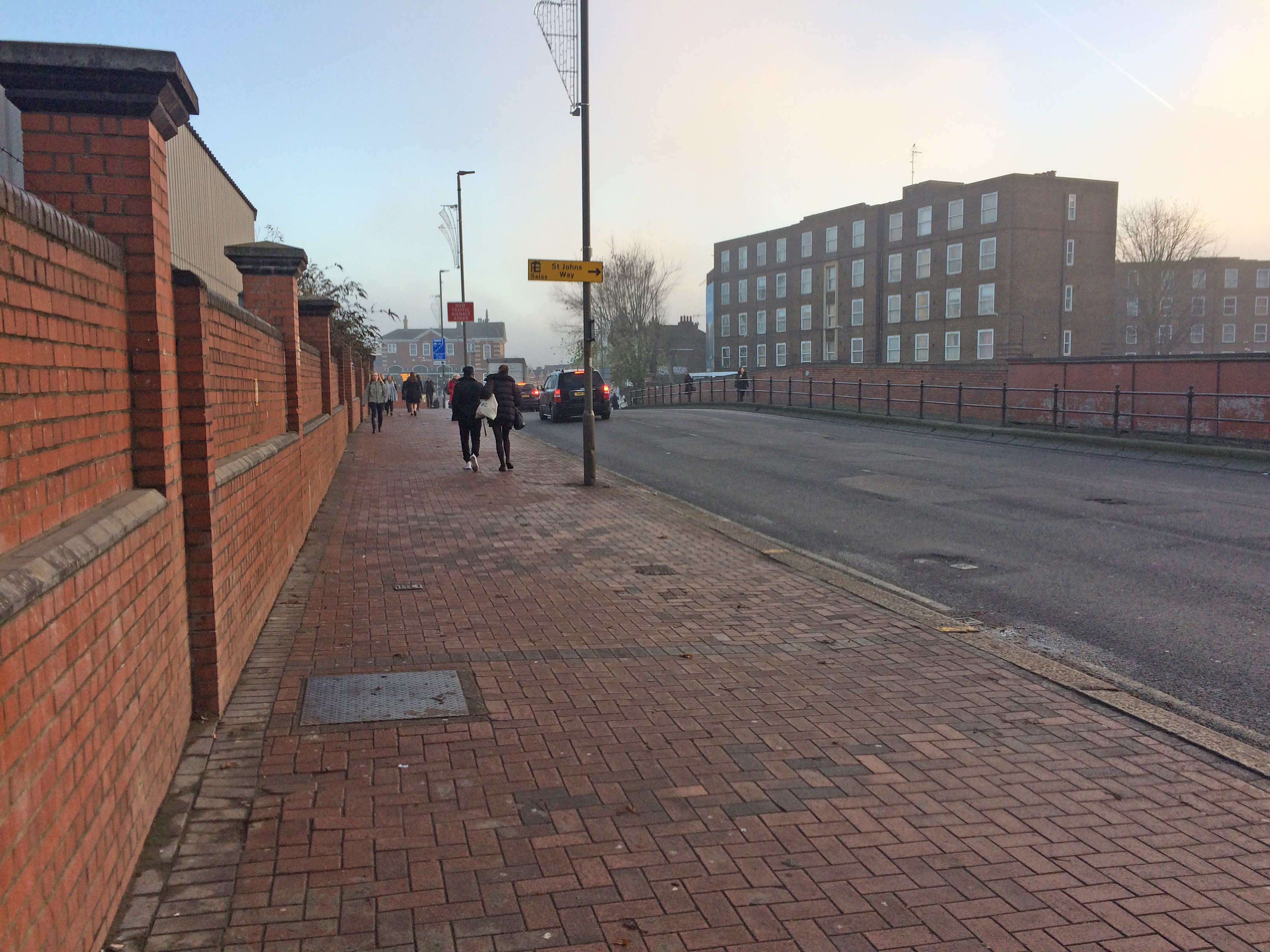
St John's Hill Bridge


Description of Works

Routine maintenance inspections of St John’s Hill Bridge highlighted severe defects to the structural elements of the structure. With no records of previous assessments, FM Conway’s Consultancy division were tasked by Wandsworth Asset Management to undertake a load assessment on the bridge. 

The assessment included an in-depth desk study, in situ sampling and testing, structural analysis and a safe working load assessment to ensure that the bridge was still fit for purpose and safe to use.

Services used on this project Structures Consultancy
Delivering Innovation

The bridge is placed over multiple railway tracks south of Clapham Junction Station and covers an area of 80 meters x 14 meters.  It is comprised of six spans and carries the A3036 Road and footways above. The structure itself was built between 1884 and 1965 over various stages, resulting in the characteristics in spans varying in materials used, length and articulation:

Spans 1 + 2:

  • Spans 1 and 2 were built in 1884 with the use of wrought iron beams, with cross sections of the beams varying throughout their length. Inspection confirmed the beams were simply supported at the West Abutment and Piers A and B. Between 1901 and 1915 the spans were extended by adding a cast iron box section to the North side.

Span 3:

  • Span 3. The Southern section of the span is comprised of in situ reinforced concrete beams that were erected as part of a replacement scheme to the existing bridge (circa 1917). The North section with pre-cast concrete is considered to have been constructed in 1967 during the erection of Span 5 and 6. Currently the span comprises of 11 beams, varying in shape. The Span is considered to be simply supported on Piers B and C.

Spans 4, 5 + 6:

  • Spans 4, 5 and 6 were built in 1967 with use of pre-cast, pre-stressed beams. Analysis of the as-built drawings show that concrete cast at the area of Pier C was discontinuous with concrete cast in the spans and that reinforcement used over the pier was laid in the layer of carriageway surface. Spans 4 - 6 were, therefore, considered as simply supported between Piers C and D, and Pier D and the East Abutment respectively.


Initially, all six spans of the bridge were to be inspected, but after careful consideration it was decided that only three spans needed to be inspected in order to inform a full assessment of the bridge.  This approach meant that the assessment was completed far more quickly, which in turn reduced the cost for the client. The team also used a ‘non-destructive’ method that reduced the time when concrete testing; this saved money for the client, as well as time for the samples to be sent out to a third party.

Marcin Naglak, Principal Engineer at FM Conway, led the inspection to visually identify defects.  The aspects looked at were: the base areas and end abutment walls, the deck soffit including bearing areas, the principal and secondary beams, the intermediate columns and piers, the bridge parapets and carriageway above.

Measuring tape and callipers were used locally while a 3D scanner was used to confirm the beam arrangement, spacing and levels stated on as-built records. The East Abutment and Intermediate Piers A and B were inspected from ground level. The Soffits of Spans 1, 2 and 3 were inspected from non-conductive mobile scaffold towers.

/files/library/images/Case studies/Structures/StJohnsHillBridge.JPG
Challenges and Solutions

The main challenge of this project was the location of the bridge and the busy 2,000 train per hour station.  FM Conway agreed that the works would take place during the night to reduce the impact to the public. Marcin Naglak had to maintain contact with Network Rail’s Controller of Site Safety (COSS) to ensure that the electricity supplies to the track were isolated for the teams to work safely.

During the inspection it was discovered that the reinforced concrete beams were incapable of carrying pedestrians and posed an immediate risk to the tracks below. The team enlisted FM Conway’s Structures division who removed the delaminated concrete as a safety precaution to prevent it falling below and damaging network rail assets. The concrete was safely removed during one of the possessions, utilising the time and quick deployment to preserve the asset, but to also save money having to revisit on a further track possession.

Once this was completed, the team conducted the desk assessment by loading in the factors inspected during the in situ visual and intrusive investigations.

Outcomes

The information gathered from the visual inspection was then used to conduct the desk study, which, in turn, resulted in the recommendations presented to the client.

It was concluded that the defects discovered were caused by a severe lack of maintenance and that nearly one hundred years of water ingress from the carriageway surface to the structural elements led to the current poor condition of the structure.

The team found that the reinforced concrete beams were incapable of carrying pedestrians and, as a precaution, resulted in the immediate closure of the footway. There were also suggestions to enlist a weight restriction on the bridge. The recommendations were made to extend the longevity of the bridge; these were divided into Short-Term (within 1 year), Medium-Term (within 2 years), Long-Term (within 3 years).